UC-SLS Lecture 9 : Assembly : Operations and Data Types
Contents
9. UC-SLS Lecture 9 : Assembly : Operations and Data Types#
9.1. Let’s start with some preliminaries about Bytes#
9.2. We need some notation#
UC-SLS:Representing information - Preliminaries: Bits, Bytes and Notation
9.2.1. Vectors of bits#
Byte a vector of 8 bits
| [b7 | b6 | b5 | b4 | b3 | b2 | b1 | b0] | |
|---|---|---|---|---|---|---|---|---|
| ALL OFF | 0 | 0 | 0 | 0 | 0 | 0 | 0 | 0 |
| ALL ON | 1 | 1 | 1 | 1 | 1 | 1 | 1 | 1 |
Natural to define value, as a non-negative integer (UINT), as the positional sum of powers of two as follows:
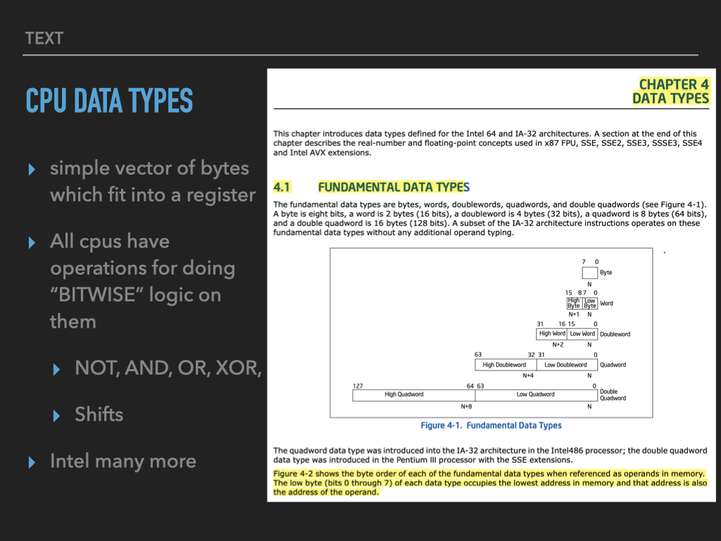
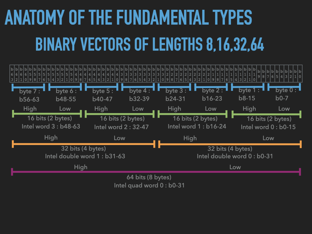
9.2.2. Beyond 8 bits#
More generally \(n\)-bit binary vector
Standard lengths are certain multiples of 8
Multiplication |
Number of Bits |
Notation |
Names |
|---|---|---|---|
\(1 \times 8\) |
8 bits |
\(X_{8}\) |
Byte, C: unsigned char |
\(2 \times 8\) |
16 bits |
\(X_{16}\) |
INTEL: Word, ARM: Half Word, C: unsigned short |
\(4 \times 8\) |
32 bits |
\(X_{32}\) |
INTEL: Double Word, ARM: Word, C: unsigned int |
\(8 \times 8\) |
64 bits |
\(X_{64}\) |
INTEL: Quad Word, ARM: Double Word, C: unsigned long long |
\(16 \times 8\) |
128 bits |
\(X_{128}\) |
INTEL: Double Quad Word, ARM: Quad Word |
\(32 \times 8\) |
256 bits |
\(X_{256}\) |
? |
\(64 \times 8\) |
512 bits |
\(X_{512}\) |
? |
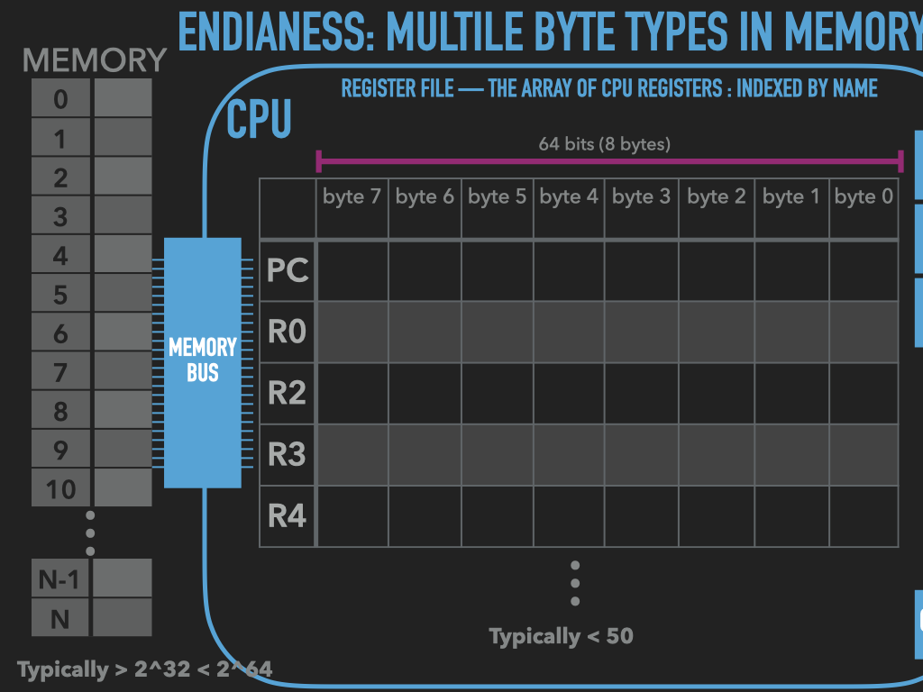
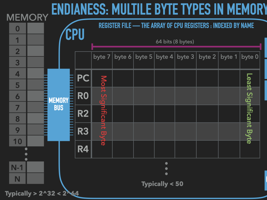
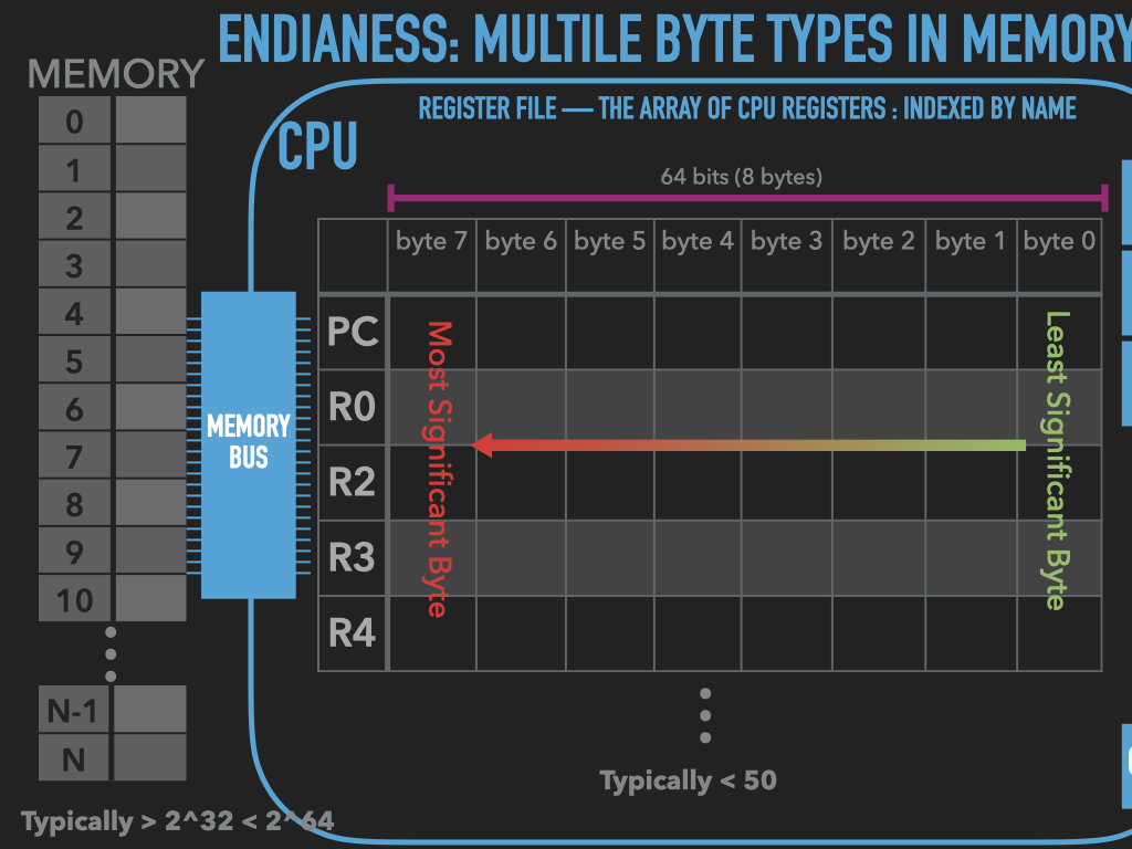
Memory is an array of bytes
Registers vary in their sizes depends on the CPU
9.3. A program is bytes and manipulates bytes#
code is represented with bytes
data is represented with bytes
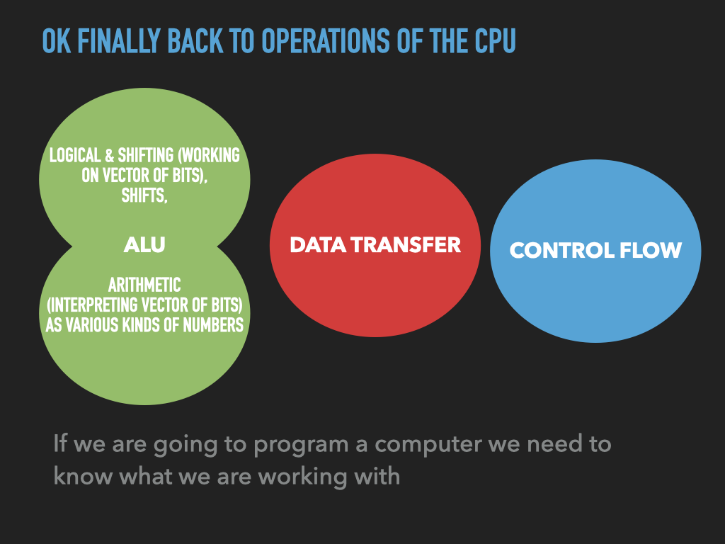
CPU operations are encoded with bytes
byte oriented operations of CPU are our building blocks
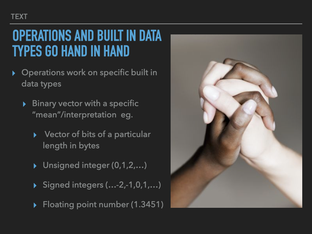
9.4. One more word about integers#
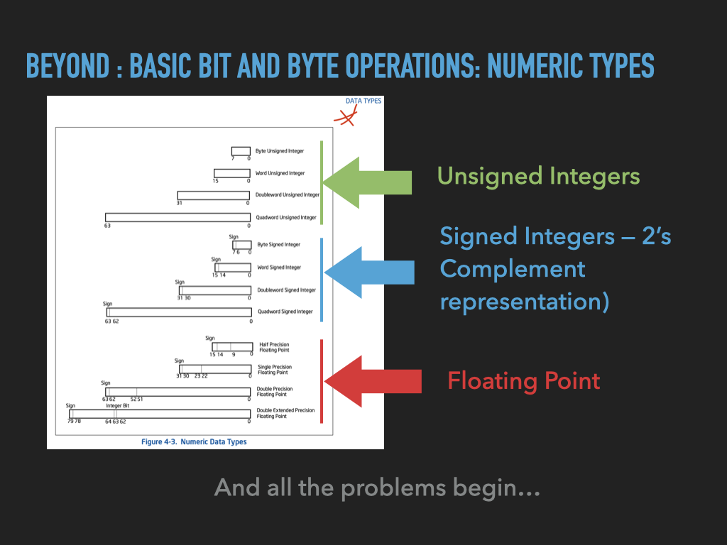
As humans we very quickly become comfortable with the idea of negative quantities
But what does negative and positive “mean” when dealing with binary vectors
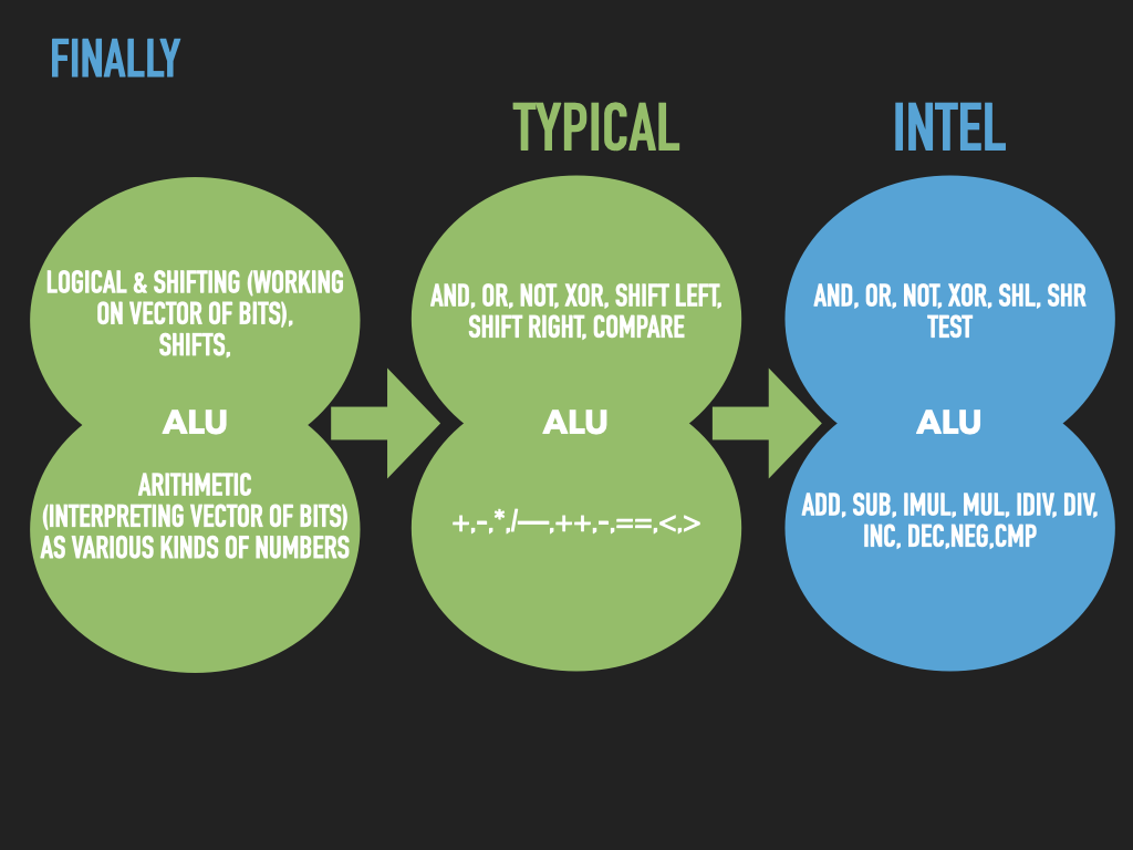
CPUs default support is for unsigned \(n\) bit integers \(0\) to \(2^{n} - 1\)
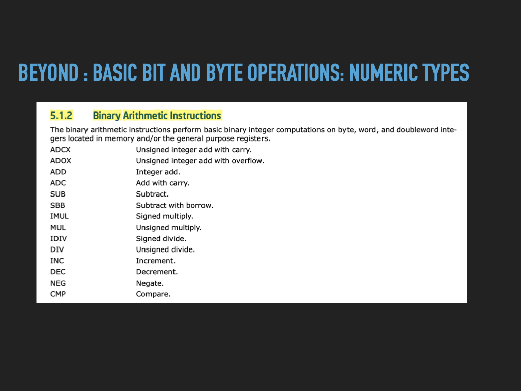
add, subtract, bitwise and, bitwise or, compare, etc
CPUs typically have special support to for signed integers
a very clever encoding
“2’s Complement” encodes a positive and negative values
\(-2^{n-1}\) to \(2^{n-1}-1\) in \(n\) bits
As Assembly programmers we will need to carefully know what instructions are sensitive
does NOT matter
add, subtract, bitwise and, bitwise or
does matter
operations that depend on comparison (eg less than, greater than)
punt on the details of 2’s complement till later
we will assume signed values and focus on when it matters


9.5. Programming Homework#
The following will get us started applying the ideas we have explored by:
introducing the basic INTEL syntax we will need to write code composed of INTEL cpu instructions
introducing the “Addressing Mode” syntax that we use to specify “operands” for our operations
learn how to use the
movINTEL instructionuse gdb to explore binaries created from our code
9.6. A simple mov.S program#
9.6.1. Setup#
create a directory
mkdir mov; cd movcreate and write
mov.Sbelowadd a
Makefileto automate assembling and linkingwe are going run the commands by hand this time to highlight the details
add our
setup.gdbto make working in gdb easiernormally you would want to track everything in git
CODE: asm - mov.S
	.intel_syntax noprefix
	.text

	.equ EXIT_SYSCALL_NR,60

	.global _start
	.type _start, @function
_start:
	mov rax, 0b1000

	mov rax, EXIT_SYSCALL_NR
	mov rdi, 2
	syscall
9.6.2. Assemble mov.S into mov.o directly with assembler (as)#
we could add
-gflag to add extra debugger information but lets skip it for now
9.6.2.1. mov.o is NOT an executable#
9.6.2.2. What kind of file is is it?#
9.6.2.3. Examine Symbol Table#
The assembler records a table, in the output object file, that containing all the symbols we created in our assembly code. In our case, the two lines of our code that introduces symbols were:
the
.equthat introduced the symbolEXIT_SYSCALL_NRthat we explicitly gave a value of decimal 60 tothe label line
start:introduced a symbol whose value is the address in memory of where ourmovinstruction will be placed
We can use the objdump -t command to see this table. It displays one line per symbol with several pieces of information per symbol.
For now, all we care about, is the first number and the name which appears at the end of the line.
The first number is the symbols value. Most of symbols we introduce will be labels (like _start). For labels the value is a location in
memory – a memory address. Note by default objdump prints values using hexadecimal notation.
Notice in our object file the symbol _start has not been assigned a location in memory yet. This is indicated by the zeros as its value.
It will be the linker’s job to assign the symbols, that are labels, their locations in memory and hence give them their final value.
9.6.3. Link mov.o to produce the binary mov with linker (ld)#
we don’t really have any other files to link
simply need to have linker organize things as per guidelines provided by the Operating Systems
these guidelines are provided in something called a linker script
You can use
ld -verboseto see the default linker script it usesif you do look at it beware the syntax is very cryptic
Use ld to link
Notice that the symbol table of the final binary executable, mov, has a value assigned for _start. This tells us that the data that we placed after the label will be located at the address that is the symbol’s value. In our case the address is 0x401000. When we use gdb, we should find at that address, is the bytes that encode the mov instruction we wrote (mov rax, 0b1000). This can be tricky at first to keep straight. A label is assigned a memory address by the linker but the byte values at the location in memory will be generated from the assembly statements we place after the label. In this way labels are just human names for location’s in memory. However, at those locations are values that give the location meaning.
Next when you use gdb poke around and try to draw a picture to clarify what is going on. Try to make sure you can understand the difference between the address of _start versus the values of the bytes at that address.
Note
Running our binary: Since we added the proper exit code we can certainly run out binary but it’s not that interesting.
$ ./mov
$ echo $?
2
9.6.4. Use debugger to explore#
To really learn something from this program we have to explore it with the debugger.`
9.6.4.1. rebuild with more debug info -g#
9.6.5. start gdb and poke around#
gdb -tui mov -x setup.gdb
Don’t just run the following command blindly. You are trying to use GDB commands to learn about how things work.
set a break point at
_startstart a process from the binary
runexamine the value of
raxand the pc (rip)What is the address of the
rip?What is the address of
_start?What does
disass _startdo?What are the values of the bytes at
_start(use the examine (x/7xb _start))?
single step on instruction (
stepi)examine
raxquit the debugger
Now try modifying the code to load a different value, rebuild and use gdb again to explore your new binary. Remember to create a binary from your code you must always rerun the assembler and linker to translate it. Writing a Makefile to automate this step will save you a lot of headaches. All of us change our code and forget to rebuild and wonder why things aren’t working ;-)
9.7. Formally getting started with Assembly Programming Syntax#
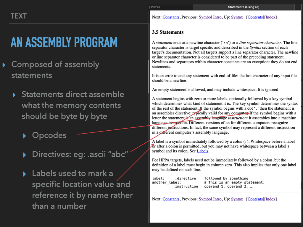
9.8. Assembly Instruction Statement Syntax#
Lets take a minute to examine the syntax of using the assembler to specify CPU operations we want done. Remember the CPU’s manual provides is with a short name called a mnemonic is the short-hand name of an operation it supports. These sometime are also called instructions.
Here is the syntax:
[label:] mnemonic [operands][ # comment ]
Anything in square brackets is optional depending on the mnemonic.
The following are the four types of Intel instructions
mnemonic- alone no explicitly defined operandsmnemonic <destination>- a single operandwhich is the destination … where the result will be stored
mnemonic <destination>, <source>- two operands
one that names a source location for input
and one that is the destination
mnemonic <destination>, <source A>, <source B>- three operandstwo that name input sources
and one that names the destination
9.8.1. Labels#
By placing a label, before an assembly instruction statement, we are introducing a symbol. This symbol marks the location where the instruction gets located in memory. We can use this symbol in other parts of our code to refer back to the location of where this instruction ends up. This is really useful when we start writing loops, conditional logic, functions etc.
9.8.2. Sources and destinations (Operand Addressing)#
When we write assembly code the operations like mov or add will need arguments. Generically we call the arguments operands.
Some operands specify where the input values for the operation should come from. Similarly other operands specify where the output value should go.
We call the inputs sources and the output destinations.
Sources and destinations must name both a location of a value and its length.
-Eg. 2 bytes at Address 0x10000 is the operand for the instruction
Lets look at this a little more closely.
9.9. Addressing Modes for sources and destinations#
lets look more closely now at the “address modes” by carefully studying the various ways we can use the
movinstructionby looking at the ways that we can specify its
operands
mov <destination>, <source>
<destination> and <source> are the operands and the mov is the mnemonic of instruction we want to encode.
9.9.1. The INTEL mov instruction#
Overwrite the <destination> with a copy of what is in the <source>
note the value that was in
<destination>is over-writtenits “gone”
the
<source>still has its version
This is actually more like copy than move!
From a high level programming perspective it is like an assignment statement
x = y;
9.9.2. destinations and sources#
Here are the various types of locations that can be a source or destination
Register (reg) – one of the processor’s registers
Memory (mem) – an address of an arbitrary memory location
Immediate (imm) – a special type of Memory location where the value is in the bytes following the opcode
You can only use Immediates as a source
Here is the valid combinations that you can have
mov <reg>, <reg>mov <reg>, <mem>mov <mem>, <reg>mov <reg>, <imm>
What is missing?
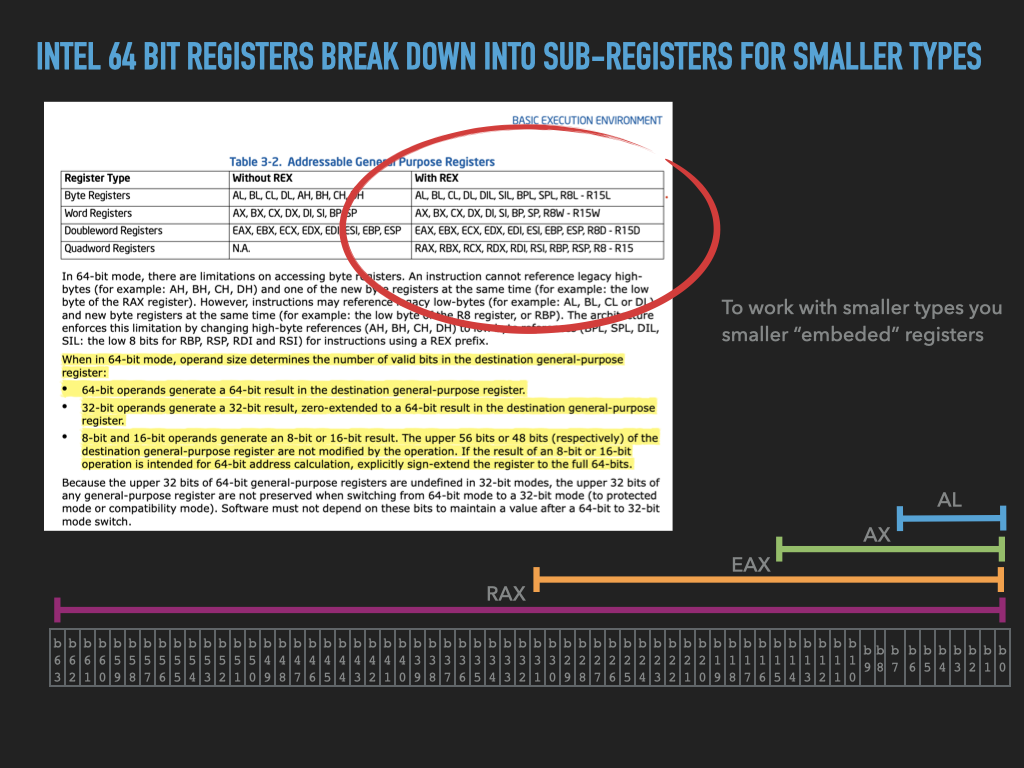
9.9.2.1. Sizes#
Register names specify size of location
The rules for mixing is a little subtle (eg moving from a smaller to larger register)
Immediates generally are 1,2,4 bytes in size
We will see memory syntax next
9.9.2.2. Specifying memory locations is subtle – Effective Address#
Here is a brief summary.
Most general form $\( EA={Base}_{reg} + ({Index}_{reg} * {Scale}) + {Displacement} \)$ where
\(Scale = \{1,2,5,8\}\)
\({Displacement}\) is 8-bit, 16-bit, or 32-bit value
\({Base}_{reg}\) and \({Index}_{reg}\) are the value in a 64-bit general-purpose register.
The components can be mixed and matched to make it easier to work with arrays and data structures of various kinds located in memory.
There are several version of syntax for these combinations
9.9.2.3. Specifying and offset/address to be used to locate the operand value#
They Gory details from the INTEL manuals – At this point this is really just for reference sake.
A lot of the subtly and confusion come from how we work with memory locations
Effective address
static location:
” Displacement: A displacement alone represents a direct (uncomputed) offset to the operand. Because the displacement is encoded in the instruction, this form of an address is sometimes called an absolute or static address. It is commonly used to access a statically allocated scalar operand.
dynamic location:
“Base: A base alone represents an indirect offset to the operand. Since the value in the base register can change, it can be used for dynamic storage of variables and data structures.”
dynamic + static “Base + Displacement: A base register and a displacement can be used together for two distinct purposes:
As an index into an array when the element size is not 2, 4, or 8 bytes
The displacement component encodes the static offset to the beginning of the array.
The base register holds the results of a calculation to determine the offset to a specific element within the array.
To access a field of a record:
the base register holds the address of the beginning of the record,
while the displacement is a static offset to the field.”
this form is really useful for stack frame records (rbp base) – more later on this
“(Index * Scale) + Displacement : This address mode offers an efficient way to index into a static array when the element size is 2, 4, or 8 bytes. The displacement locates the beginning of the array, the index register holds the subscript of the desired array element, and the processor automatically converts the subscript into an index by applying the scaling factor.”
“Base + Index + Displacement : Using two registers together supports either
a two-dimensional array (the displacement holds the address of the beginning of the array) or
one of several instances of an array of records (the displacement is an offset to a field within the record).”
“Base + (Index * Scale) + Displacement : Using all the addressing components together allows efficient indexing of a two-dimensional array when the elements of the array are 2, 4, or 8 bytes in size.”
PC Relative: “RIP + Displacement : In 64-bit mode, RIP-relative addressing uses a signed 32-bit displacement to calculate the effective address of the next instruction by sign-extend the 32-bit value and add to the 64-bit value in RIP.”
9.9.3. Intel Syntax examples#
When we specify a memory location we must also clearly state how many bytes we want to work with at that location. Eg. the size in bytes of the value at the memory location. To do this, in addition to the address expression, we must also prefix it with the appropriate size syntax as follows:
<BYTE|WORD|DWORD|QWORD> PTR [displacement]wheredisplacementis either a number or symbolthe assembler will often let you skip the
<TYPE> PTRif it can figure it outbut I think it is safer to be verbose
the assembler will let you skip the
[]if you are using a labelbut again I think it is more clear that you mean that value at the label
OFFSET [symbol]can be used as a source if you want to use the address of the symbol itself as a number<BYTE|WORD|DWORD|QWORD> PTR [RegBase + displacement]<BYTE|WORD|DWORD|QWORD> PTR [RegIdx * scale + displacement]<BYTE|WORD|DWORD|QWORD> PTR [RegBase + RegIdx * scale + displacement]
9.10. Move examples#
So in reality we see that there are many different ways of using mov to move data. The following demonstrates several of the different types.
Over the next few lectures we will use various different forms of mov
CODE: asm - movexamples.s
	# Example code that illustrates various ways of
	# working with data in memory.
	# 1) Assemble this code eg. as -g mov.s -o mov.o
	# 2) Link into an executable eg. ld -g mov.o -o mov
	#
	# I suggest you then use gdb to single step the instructions --
	# executing the instructions one by one. But before you go on
	# to then next instruction do the following
	#   1) display the destination register
	#   2) examine the value in memory you think it will be loaded with
	#   3) write down on a paper your guess
	#   4) step the instruction
	#   5) display the destination register and see if you were right
	#      if not try and figure out why not

	.intel_syntax noprefix

	# Quick discussion about sections and organizing our memory into
        # data and text portions

	# Sections let us seperate out our programs memory into
	# distinct non-overlaping areas.  The two sections
	# we will use are .text and .data
	#
	# .text is for opcodes     (bytes to be executed)
	# .data is for data values (bytes to be read and written by our program
	#
	# We switch sections with the .section directive
	# All bytes for a section will be grouped together by the linker and
	# placed in a single contingous area of memory when a process is created
	#
	# Every assembly file can add bytes to either section
	# You can switch sections at any point in your assembly files

	# Switch current section to the data section
	.section .data

	# set a label MYBYTES to the begin of the following bytes
MYBYTES:
	.quad 0xdeadbeeffeedface   # reserve 8 bytes initialized to
	                           # the value indicated in hex

	# Switch current section to the text section
	.section .text

	.global _start                # expose this symbol to the linker
_start:
	# examples of loading registers of different sizes from
	# data at a label
	xor r8, r8                    # r8 = 0  (clear r8)
	mov r8,  QWORD PTR [MYBYTES]  # load  r8 with 8 byte vector at MYBYTES
	mov r8d, DWORD PTR [MYBYTES]  # load r8d with 4 byte vector at MYBYTES
	mov r8w, WORD PTR [MYBYTES]   # load r8w with 2 byte vector at MYBYTES
	mov r8b, BYTE PTR [MYBYTES]   # load r8b with 1 byte vector at MYBYTES

	# example of loading registers of differrent sizes using another register
	# that we first load with the address of the data
	xor rax, rax		      # rax = 0 (clear rax)
	mov rax, OFFSET MYBYTES       # rax = &MYBYTES (set rax to the address)

	mov rbx, QWORD PTR [rax]
	mov ecx, DWORD PTR [rax]
	mov dx,  WORD  PTR [rax]
	mov sil, BYTE  PTR [rax]

	# example of using another register to act as a index
	# Effective Address = rax + r9 * 1
	# where the current value in rax is added to the value in r9 times 1
	# 1 is called the scale when one we can skip it but show it to be
	# explicit. Other valid values for scale are 2, 4, and 8
	xor r9,r9
	mov r10b, BYTE PTR [rax + r9*1]
	inc r9
	mov r11b, BYTE PTR [rax + r9*1]
	inc r9
	mov r12b, BYTE PTR [rax + r9*1]
	inc r9
	mov r13b, BYTE PTR [rax + r9*1]

	# same as above but using a label
	xor r9,r9
	mov r10b, BYTE PTR [MYBYTES + r9*1]
	inc r9
	mov r11b, BYTE PTR [MYBYTES + r9*1]
	inc r9
	mov r12b, BYTE PTR [MYBYTES + r9*1]
	inc r9
	mov r13b, BYTE PTR [MYBYTES + r9*1]

	# example of using scale = 2
	xor r9, r9
	mov r14w, WORD PTR [rax + r9 * 2]
	inc r9
	mov r15w, WORD PTR [rax + r9 * 2]

	# example of using a base reg, index, and displacement
	xor r9, r9
	mov r14w, WORD PTR [rax + r9 * 2 + 1]
	inc r9
	mov r15w, WORD PTR [rax + r9 * 2 + 1]

	# following calls the UNIX OS exit system call
	# so that we terminate nicely

	.equ EXIT_SYSCALL_NR,60
	mov rax, EXIT_SYSCALL_NR
	mov rdi, 0
	syscall
9.11. Test your knowledge#
Note
We can use the .data directive in our assembly source code to switch sections. Then we can add bytes to the data section of our process’s memory. Labels in the data section work exactly the same as in the text section. Labels let us refer to the bytes following the label. Eg. x: .quad 142 means reserve 8 bytes and initialize those 8 bytes with the decimal value 142. Finally, the symbol x will be assigned the address where these bytes end up.
With the above knowledge can you figure out what this code is doing and explain how it works?
        .intel_syntax noprefix
        .data
x:      .quad 142
y:      .quad 4200
sum:    .quad

        .text
        .global _start
_start:
        mov rax, QWORD PTR [x]
        add rax, QWORD PTR [y]
        mov QWORD PTR [sum], rax

        mov rax, 60
        mov rdi, 0
        syscall
To figure this out you will want to assemble, link and explore the resulting binary in gdb. In gdb to examine the bytes at a label in the data area you will need to add an & in front of the symbol. Eg To examine the bytes at x you could use the following gdb commands:
x/8xb & xprint 8 bytes starting at the address of x in hexadecimal formatx/1gd & xprint the 8 bytes at the address of x as a single 8 byte integer
Finally, can you extend the code to calculate the number of 1’s in the sum and save the result somewhere in the data section?